The module lifecycle stage: General Availability
The module has requirements for installation
This guide describes how to configure the virtualization module and manage its cluster-wide resources.
Administrator permissions also cover project resources, which are described in the user guide.
Module parameters
You configure the virtualization module in the ModuleConfig resource. The following example sets the Ingress controller class, the image storage, and the subnet for virtual machines:
- Using the CLI
- Using the web interface
Apply the manifest with the required parameters:
apiVersion: deckhouse.io/v1alpha1
kind: ModuleConfig
metadata:
  name: virtualization
spec:
  enabled: true
  version: 1
  settings:
    ingressClass: nginx # Optional parameter.
    dvcr:
      storage:
        persistentVolumeClaim:
          size: 50G
          storageClassName: rv-thin-r1
        type: PersistentVolumeClaim
    virtualMachineCIDRs:
- 10.66.10.0/24- Go to the System tab, then to Deckhouse → Modules.
- Select the
virtualizationmodule from the list. - In the window that opens, select the Configuration tab.
- To show the settings, click the Advanced settings toggle.
- Set the parameters. The form field names match the parameter names in YAML.
- Click Save.
Enabling and disabling the module
The .spec.enabled parameter controls the module state. Set it to true to enable the module, or to false to disable it.
Disabling the module stops every system component that creates and runs virtual machines (VMs), so the module can’t be disabled by default.
To make it possible, add the modules.deckhouse.io/allow-disabling annotation set to true to the virtualization ModuleConfig.
Before disabling the module, prepare the cluster:
-
Delete all module resources, including virtual machines, disks, and images.
-
Verify that no active resources are left in the cluster:
d8 k get virtualization -A
d8 k get virtualization-cluster
Then edit the virtualization ModuleConfig:
apiVersion: deckhouse.io/v1alpha1
kind: ModuleConfig
metadata:
  name: virtualization
  annotations:
    modules.deckhouse.io/allow-disabling: "true"
spec:
  enabled: false
  version: 1
  settings:
    # Specify the existing settings.
If the module resources aren’t deleted, disabling the module can lead to data loss.
Configuration version
The .spec.version parameter defines the settings schema version. The parameter structure can change between versions; for the current values, see the module settings.
Ingress settings
Virtual machine images are uploaded to the cluster through an Ingress controller, whose class is defined by the .spec.settings.ingressClass parameter.
The parameter is optional: if you leave it unset, the module uses the global value from the Deckhouse Platform (DP) configuration.
Set it only when image upload requires a separate Ingress controller.
Example:
spec:
  settings:
    ingressClass: nginx
Large virtual machine images take a long time to upload over a slow connection, and restarting or updating the Ingress controller interrupts the upload. To avoid this, increase the worker shutdown timeout in the IngressNginxController resource.
Example:
apiVersion: deckhouse.io/v1
kind: IngressNginxController
metadata:
  name: nginx
spec:
  config:
    worker-shutdown-timeout: 1800s  # 30 minutes or more, if required.
Network settings
The .spec.settings.virtualMachineCIDRs block lists the subnets in CIDR notation from which DP assigns IP addresses to virtual machines, either automatically or on request.
Specify the subnet start address aligned to the mask, for example 192.168.1.192/27, not an arbitrary address from the range.
Example:
spec:
  settings:
    virtualMachineCIDRs:
      - 10.66.10.0/24
      - 10.66.20.0/24
      - 10.77.20.0/16
The first and the last address of each subnet are reserved and never assigned to virtual machines. For example, in the 10.66.10.0/24 subnet, the 10.66.10.0 and 10.66.10.255 addresses are unavailable.
You can leave the block unset. The module still starts, but you can no longer work with virtual machine addresses:
- You can’t create or use the VirtualMachineIPAddress resource.
- A virtual machine can’t request the
Mainnetwork in the.spec.networksparameter. - The
.spec.networksparameter of a virtual machine can’t be empty.
The subnets in the .spec.settings.virtualMachineCIDRs block must not overlap with the cluster node subnets, the service subnet, or the pod subnet (podCIDR).
You can’t delete a subnet if addresses from it are already assigned to virtual machines. You also can’t clear the block once it’s set.
Virtual machine image storage
DP stores virtual machine images in an internal container image storage (DVCR) that resides on a persistent volume of the cluster. Images travel from there to virtual machine disks, so the size of the volume determines how many images fit into the cluster.
Size and storage class
Set the volume size and the storage class in the .spec.settings.dvcr.storage block. To expand the storage, increase the volume size.
After the volume is created, you can’t reduce its size or change its storage class.
Storage classes for images and disks
The project owner chooses the storage class for an image or a disk. You can limit that choice and set a default class. The .spec.settings.virtualImages block covers images, and the .spec.settings.virtualDisks block covers disks.
Example:
spec:
  settings:
    virtualImages:
      allowedStorageClassSelector:
        matchNames:
          - sc-1
          - sc-2
      defaultStorageClassName: sc-1
    virtualDisks:
      allowedStorageClassSelector:
        matchNames:
          - sc-3
      defaultStorageClassName: sc-3
Both blocks work the same way and both are optional. The allowedStorageClassSelector.matchNames parameter lists the classes allowed in the VirtualImage and VirtualDisk specification, and defaultStorageClassName sets the class for resources where the .spec.persistentVolumeClaim.storageClassName parameter isn’t set.
Cleaning up image storage
When images and disks are deleted from the cluster, their data remains in DVCR for some time. To keep the storage from filling up with stale data, DP runs garbage collection on a schedule.
By default, it runs daily at 02:00. To set your own schedule, use the .spec.settings.dvcr.gc.schedule parameter in the virtualization ModuleConfig.
While garbage collection is running, the storage works in read-only mode, so creating images and disks is postponed until it completes.
- Using the CLI
- Using the web interface
Example configuration with a custom schedule:
apiVersion: deckhouse.io/v1alpha1
kind: ModuleConfig
metadata:
  name: virtualization
spec:
  # ...
  settings:
    dvcr:
      gc:
        schedule: "0 20 * * *"
  # ...
To see how much space is occupied and which data will be removed during the next collection, run:
d8 k -n d8-virtualization exec deploy/dvcr -- dvcr-cleaner gc checkExample output:
Found 2 cvi, 5 vi, 1 vd manifests in registry
Found 1 cvi, 5 vi, 11 vd resources in cluster
  Total     Used    Avail     Use%
36.3GiB  13.1GiB  22.4GiB      39%
Images eligible for cleanup:
KIND                   NAMESPACE            NAME
ClusterVirtualImage                         debian-12
VirtualDisk            default              debian-10-root
VirtualImage           default              ubuntu-2404
- Go to the System tab, then to Deckhouse → Modules.
- Select the
virtualizationmodule from the list. - In the window that opens, on the Configuration tab, enable the Advanced settings toggle.
- In the Disk and ISO image storage block, set the schedule in the Cleanup schedule in Cron format field.
- Click Save.
Images
An image holds the contents of a disk that project owners use to create virtual machine disks. A cluster image, ClusterVirtualImage, is available in every namespace and project of the cluster, so an image uploaded once serves all projects at once.
An image appears in the cluster in three steps:
- The administrator creates a ClusterVirtualImage resource and specifies a data source in it.
- DP downloads the image from that source to the internal storage (DVCR).
- The downloaded image becomes available for creating disks.
The image source can be an HTTP server hosting the image file, a container image registry, or a file on your computer that you upload from the command line. You can also create an image from another image, from a virtual machine disk, or from a disk snapshot.
The PHASE column in the d8 k get cvi output shows the progress of image creation; for its values, see the .status.phase field. To follow the creation in real time, add the -w flag. If an image stays not ready for a long time, check the .status.conditions block and the d8 k describe cvi output for the reason.
Until an image reaches the Ready phase, you can change its .spec block, and the download restarts after each change. For a ready image, the .spec block can no longer be changed. For all image parameters, see ClusterVirtualImage.
Image types and formats
There are two types of images:
- ISO image: An installation image used for the initial installation of an operating system (OS). OS vendors publish such images and use them to install the OS on physical and virtual servers.
- Disk image with a preinstalled system: Contains an OS that is already installed and configured, and is ready to work as soon as the virtual machine (VM) is created. Distribution vendors publish such images, or you can build them yourself.
Distribution vendors publish ready-made images with a preinstalled system. The following table lists their download pages and the users configured in those images by default:
| Distribution | Default user |
|---|---|
| AlmaLinux | almalinux |
| AlpineLinux | alpine |
| AltLinux | altlinux |
| AstraLinux | astra |
| CentOS | cloud-user |
| Debian | debian |
| Rocky | rocky |
| Ubuntu | ubuntu |
DP accepts image files in the following formats:
qcow2rawvmdkvdivhdvhdx
You can provide an image compressed with gz, xz, or zst. DP unpacks it during the upload.
DP detects the image type and size on its own and records them in the resource status. There are two sizes, and both appear in the d8 k get cvi -o wide output:
STOREDSIZE: The space the image occupies in the storage. For an image uploaded in a compressed form, it’s smaller than the unpacked size. Use this column to estimate how much space the images take in DVCR.UNPACKEDSIZE: The size of the image after unpacking. It defines the minimum size of a disk that can be created from this image.
When creating a disk from an image, specify a size no smaller than the UNPACKEDSIZE value.
If you don’t specify a size, the disk is created with exactly the unpacked size of the image.
Creating a cluster image from an HTTP server
The simplest way to create an image is to provide a link to a file hosted on an HTTP server.
- Using the CLI
- Using the web interface
-
Create a ClusterVirtualImage resource:
d8 k apply -f - <<EOF apiVersion: virtualization.deckhouse.io/v1alpha2 kind: ClusterVirtualImage metadata: name: ubuntu-24-04 spec: # Source for the image. dataSource: type: HTTP http: url: https://cloud-images.ubuntu.com/noble/current/noble-server-cloudimg-amd64.img EOF -
Verify that the image is created:
d8 k get clustervirtualimage ubuntu-24-04

# Short form of the command.
d8 k get cvi ubuntu-24-04
Example output:
NAME           PHASE   CDROM   PROGRESS   AGE
ubuntu-24-04   Ready   false   100%       23h
To make DP verify the downloaded file against a checksum, add the checksum block to the source. If the file doesn’t match any of the specified checksums, the image moves to the Failed phase.
- Go to the System tab, then to Virtualization → Cluster images.
- Click Create, then select By link in the Source block.
- In the Image name field, enter the image name.
- In the URL field, specify the link to the image.
- Click Create.
- Wait until the image reaches the Ready state.
Creating a cluster image from a container image registry
DP can pull an image from an external container image registry, but the disk file must be located in the container image under the /disk path. The following steps show how to prepare such a container image and create a cluster image from it.
- Using the CLI
- Using the web interface
-
Download the image file to your local machine:
curl -L https://cloud-images.ubuntu.com/minimal/releases/noble/release/ubuntu-24.04-minimal-cloudimg-amd64.img -o ubuntu2404.img -
Create a
Dockerfilewith the following contents:FROM scratch COPY ubuntu2404.img /disk/ubuntu2404.img -
Build the container image. The example uses the docker.com registry, which requires an account and a configured environment:
docker build -t docker.io/<USERNAME>/ubuntu2404:latestWhere
<USERNAME>is the username you specified when registering in the registry. -
Push the built container image to the registry:
docker push docker.io/<USERNAME>/ubuntu2404:latest -
Create a ClusterVirtualImage resource that points to the container image:
d8 k apply -f - <<EOF
apiVersion: virtualization.deckhouse.io/v1alpha2
kind: ClusterVirtualImage
metadata:
  name: ubuntu-2404
spec:
  dataSource:
    type: ContainerImage
    containerImage:
      image: docker.io/<USERNAME>/ubuntu2404:latest
EOF
DP works only with registries that have TLS enabled. If the registry uses its own certificate authority, provide the certificate chain in the caBundle parameter, and take the credentials for a private registry from the secret specified in the imagePullSecret parameter.
- Go to the System tab, then to Virtualization → Cluster images.
- Click Create, then select From registry in the Source block.
- In the Image name field, enter the image name.
- In the Image in container registry field, specify the link to the image.
- Click Create.
- Wait until the image reaches the Ready state.
Uploading a cluster image from the command line
If the image file is on your computer, upload it directly. DP creates a temporary upload endpoint for this and waits for the data.
- Using the CLI
- Using the web interface
-
Create a ClusterVirtualImage resource with the
Uploadsource:d8 k apply -f - <<EOF apiVersion: virtualization.deckhouse.io/v1alpha2 kind: ClusterVirtualImage metadata: name: some-image spec: # Image source settings. dataSource: type: Upload EOFThe resource moves to the
WaitForUserUploadphase and is ready to accept the file. Start the upload within 10 minutes, otherwise the resource moves to theFailedphase and you have to create it again. -
Get the addresses that accept the file:
d8 k get cvi some-image -o jsonpath="{.status.imageUploadURLs}" | jqExample output:
{
  "external":"https://virtualization.example.com/upload/<SECRET_URL>",
  "inCluster":"http://10.222.165.239/upload"
}
Use the
inClusteraddress if you upload the file from one of the cluster nodes, andexternalin all other cases. -
Upload the file to the selected address. The example first downloads the Cirros image and then sends it to the cluster:
curl -L http://download.cirros-cloud.net/0.5.1/cirros-0.5.1-x86_64-disk.img -o cirros.img
curl https://virtualization.example.com/upload/<SECRET_URL> --progress-bar -T cirros.img | cat
Where
<SECRET_URL>is the last part of the address from the previous step. -
Verify that the image has reached the
Readyphase:d8 k get cvi some-imageExample output:
NAME         PHASE   CDROM   PROGRESS   AGE
some-image   Ready   false   100%       1m
You can also verify the uploaded file against a checksum. To do this, specify the checksum block in the data source.
- Go to the System tab, then to Virtualization → Cluster images.
- Click Create, then select Upload in the Source block.
- In the Image name field, enter the image name.
- In the Upload file block, drag the file to the highlighted area or click select on your computer.
- Select the file in the file manager that opens.
- Click Create.
- Wait until the image reaches the Ready state.
Virtual machine classes
A virtual machine (VM) class defines what the project owner doesn’t configure: the virtual CPU model, the allowed combinations of cores and memory, and the nodes where a VM can run. These rules are described by the VirtualMachineClass resource, which you use to control how project workloads are distributed across cluster nodes.
On the initial installation, the module creates the generic class with the Nehalem CPU model. This model is old but supported by any modern CPU, so VMs of this class start on any cluster node and migrate between nodes without restrictions.
The generic class matches a CPU with the smallest instruction set, so it isn’t suitable for production workloads.
Once all nodes are added to the cluster and configured, create at least one class with the Discovery CPU type. DP selects an instruction set available on all nodes at once, so virtual machines can make fuller use of the CPUs while still being able to migrate between nodes. The instruction set is fixed when the resource is created and doesn’t change as nodes are added or removed.
For an example of such a class, see vCPU Discovery configuration example.
Classes exist at the cluster level. To list them, run the following command:
d8 k get virtualmachineclassExample output:
NAME      PHASE   ISDEFAULT   AGE
generic   Ready               6d1h
In any class, you can change everything except the .spec.cpu block, because the CPU model is fixed when the resource is created. You can both modify and delete the generic class, but it won’t be created again, because the module adds it only on the initial installation.
The project owner specifies the class in the .spec.virtualMachineClassName parameter of a virtual machine:
apiVersion: virtualization.deckhouse.io/v1alpha2
kind: VirtualMachine
metadata:
  name: linux-vm
spec:
  virtualMachineClassName: generic # Name of the VirtualMachineClass resource.
  # ...
Default VirtualMachineClass
You can designate one of the classes as the default. DP inserts its name into the .spec.virtualMachineClassName parameter if the project owner doesn’t specify a class.
The default class is marked with the virtualmachineclass.virtualization.deckhouse.io/is-default-class annotation set to true. A cluster can have only one such class, so to designate a new one, first remove the annotation from the current one.
Don’t add the annotation to the generic class, because a module update can remove it. Create your own class and designate it as the default instead.
-
Check which classes exist in the cluster:
d8 k get vmclassExample output with no default class:
NAME PHASE ISDEFAULT AGE generic Ready 1d host-passthrough-custom Ready 1d -
Designate the default class:
d8 k annotate vmclass host-passthrough-custom virtualmachineclass.virtualization.deckhouse.io/is-default-class=true -
Verify that the annotation is set:
d8 k get vmclassExample output:
NAME                      PHASE   ISDEFAULT   AGE
generic                   Ready               1d
host-passthrough-custom   Ready   true        1d
From now on, virtual machines created without a class get the host-passthrough-custom class.
VirtualMachineClass settings
A class consists of three blocks, each responsible for its own group of settings:
- Using the CLI
- Using the web interface
Describe the class in a VirtualMachineClass resource:
apiVersion: virtualization.deckhouse.io/v1alpha2
kind: VirtualMachineClass
metadata:
  name: <VMCLASS_NAME>
  # The annotation designates the class as the default one. It's optional.
  # annotations:
  #   virtualmachineclass.virtualization.deckhouse.io/is-default-class: "true"
spec:
  # Virtual CPU parameters. The block is required and can't be changed after the resource is created.
  cpu: ...

  # Rules for placing virtual machines on nodes. The block is optional.
  # Changes apply to all VMs of this class.
  nodeSelector: ...

  # Resource allocation policy for virtual machines. The block is optional.
  # Changes apply to all VMs of this class.
  sizingPolicies: ...
Where <VMCLASS_NAME> is the name of the class you’re creating.
- Go to the System tab, then to Virtualization → VM classes.
- Click Create.
- In the form that opens, enter the VM class name in the Name field.
The blocks are described separately in the following sections.
Virtual processor
The .spec.cpu block defines the CPU that the guest OS sees. It also determines which nodes a VM can migrate between.
The .spec.cpu block can’t be changed after the resource is created. To use a different CPU, create a new class.
The following examples cover each CPU type.
-
A set of CPU instructions required for a VM. Set with the
Featurestype:spec: cpu: features: - vmx type: FeaturesTo configure the vCPU in the web interface, in the VM class creation form:
- In the CPU settings block, select
Featuresin the Type field. - In the Required set of supported instructions field, select the instructions you need.
- Click Create.
- In the CPU settings block, select
-
A universal CPU for a given set of nodes. Set with the
Discoverytype:spec: cpu: discovery: nodeSelector: matchExpressions: - key: node-role.kubernetes.io/control-plane operator: DoesNotExist type: DiscoveryTo do the same in the web interface, in the VM class creation form:
- In the CPU settings block, select
Discoveryin the Type field. - Click Add in the Conditions for creating a universal CPU → Labels and expressions block.
- Set Key, Operator, and Value. They correspond to the
.spec.cpu.discovery.nodeSelectorparameter. - Press Enter to confirm the key parameters.
- Click Create.
- In the CPU settings block, select
-
A CPU close to the node CPU. Set with the
Hosttype. The guest OS gets almost the full instruction set of the node, so performance is higher than with a fixed model. A VM of this class migrates only between nodes with similar CPUs. For example, migration between nodes with Intel and AMD CPUs isn’t possible, and neither is migration between CPU generations with different instruction sets.spec: cpu: type: HostTo do the same in the web interface, in the VM class creation form:
- In the CPU settings block, select
Hostin the Type field. - Click Create.
- In the CPU settings block, select
-
The node CPU without changes. Set with the
HostPassthroughtype. A VM of this class migrates only to a node whose CPU exactly matches the CPU of the source node.spec: cpu: type: HostPassthroughTo do the same in the web interface, in the VM class creation form:
- In the CPU settings block, select
HostPassthroughin the Type field. - Click Create.
- In the CPU settings block, select
-
A specific CPU model with a known instruction set. Set with the
Modeltype. First, check which models the target node supports:d8 k get nodes <NODE_NAME> -o json | jq '.metadata.labels | to_entries[] | select(.key | test("cpu-model.node.virtualization.deckhouse.io")) | .key | split("/")[1]' -rWhere
<NODE_NAME>is the name of a cluster node.Example output:
Broadwell-noTSX
Broadwell-noTSX-IBRS
Haswell-noTSX
Haswell-noTSX-IBRS
IvyBridge
IvyBridge-IBRS
Nehalem
Nehalem-IBRS
Penryn
SandyBridge
SandyBridge-IBRS
Skylake-Client-noTSX-IBRS
Westmere
Westmere-IBRS
Then specify the selected model in the class specification:
spec:
  cpu:
    model: IvyBridge
    type: Model
To do the same in the web interface, in the VM class creation form:
- In the CPU settings block, select
Modelin the Type field. - In the Model field, select the CPU model.
- Click Create.
- In the CPU settings block, select
vCPU Discovery configuration example
The following example shows how to choose the processor types in a cluster with heterogeneous nodes.
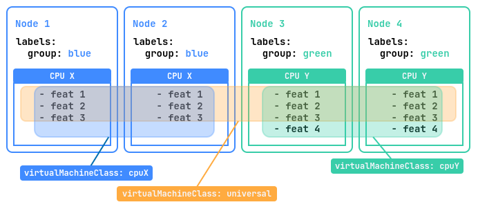
The example below uses a cluster of four nodes. Two nodes labeled group=blue are equipped with the “CPU X” processor with three instruction sets, and the other two labeled group=green have the newer “CPU Y” processor with four sets.
A CPU instruction set is every command the processor can execute, from addition to memory operations. The set determines which programs run and how fast, and it differs between CPU generations.
Three classes suit such a cluster:
universal: VMs start on any node and migrate between all four. DP takes the instruction set common to both processors, so compatibility is maximal, while some capabilities of “CPU Y” stay unused.cpuX: VMs start only on nodes with “CPU X” and migrate between them, using all instructions of that processor.cpuY: The same for nodes with “CPU Y”.
The classes for such a cluster look as follows:
---
apiVersion: virtualization.deckhouse.io/v1alpha2
kind: VirtualMachineClass
metadata:
  name: universal
spec:
  cpu:
    # An empty discovery means that all cluster nodes are taken into account.
    discovery: {}
    type: Discovery
---
apiVersion: virtualization.deckhouse.io/v1alpha2
kind: VirtualMachineClass
metadata:
  name: cpuX
spec:
  cpu:
    discovery:
      nodeSelector:
        matchExpressions:
          - key: group
            operator: In
            values: ["blue"]
    type: Discovery
---
apiVersion: virtualization.deckhouse.io/v1alpha2
kind: VirtualMachineClass
metadata:
  name: cpuY
spec:
  cpu:
    discovery:
      nodeSelector:
        matchExpressions:
          - key: group
            operator: In
            values: ["green"]
    type: Discovery
Placement across nodes
The optional .spec.nodeSelector block limits the set of nodes where virtual machines (VMs) of this class run. Nodes are selected by labels:
spec:
  nodeSelector:
    matchExpressions:
      - key: node.deckhouse.io/group
        operator: In
        values:
          - green
A change to the .spec.nodeSelector block affects all virtual machines of the class at once. Those running on nodes that no longer match the new conditions have to be moved:
- In commercial DP editions, DP migrates such VMs to suitable nodes.
- In DP Open, the VMs are restarted, and the restart time depends on the
.spec.disruptions.restartApprovalModeparameter of the virtual machine, which defaults toManualand requires the project owner’s approval.
To do the same in the web interface, in the VM class creation form:
- Click Add in the Conditions for scheduling VMs on nodes → Labels and expressions block.
- Set Key, Operator, and Value. They correspond to the
.spec.nodeSelectorparameter. - Press Enter to confirm the key parameters.
- Click Create.
Sizing policy
The .spec.sizingPolicies block defines which combinations of cores, core fraction, and memory are allowed for virtual machines (VMs) of this class.
Changes to the .spec.sizingPolicies block affect existing virtual machines.
For virtual machines that no longer meet the new requirements, the SizingPolicyMatched condition in the .status.conditions block gets the False status.
When defining policies, take the CPU topology of virtual machines into account.
A policy consists of a list of rules, each applying to its own range of cores. The range is set in the required cores block, and ranges of different rules must not overlap, otherwise DP rejects the class.
A valid structure, where the ranges follow one another without overlapping:
- cores:
    min: 1
    max: 4
  # ...
- cores:
    min: 5 # The next range starts one above the previous max.
    max: 8
An invalid structure, where the value 4 falls into two ranges at once:
- cores:
    min: 1
    max: 4
  # ...
- cores:
    min: 4
    max: 8
DP doesn’t forbid gaps between ranges, but a virtual machine whose number of cores falls outside every range is left without a policy. For this reason, start each range with the value that follows the max of the previous one.
Within a range, you set the requirements for memory and for the core fraction:
memory: The minimum and maximum amount of memory. Set either for the whole range or per core, in the nestedmemory.perCoreblock.coreFractions: The list of allowed core fractions, for example[25, 50, 100]for 25%, 50%, and 100%. If the project owner sets thecoreFractionparameter of a virtual machine explicitly, the value must come from this list.defaultCoreFraction: The core fraction that a virtual machine gets ifcoreFractionisn’t set in it. The value must be in thecoreFractionslist. If the parameter isn’t specified, 100% applies.
A rule with neither memory nor coreFractions doesn’t limit anything, so set at least one of them.
In commercial DP editions, you can set the defaultCoreFraction parameter to Auto. In that case, the core fraction for VMs without an explicit coreFraction is chosen by vertical autoscaling. Auto is a mode, not a share of a core, so it must not appear in the coreFractions list.
spec:
  sizingPolicies:
    - cores:
        min: 1
        max: 8
      coreFractions: [10, 25, 50, 100]
      defaultCoreFraction: Auto
The Auto value is accepted only when both capabilities are available:
- Vertical autoscaling of virtual machines, which is enabled automatically in commercial DP editions when the
vertical-pod-autoscalermodule is enabled. - Changing the number of cores and the amount of memory without a restart, which is enabled by the
HotplugCPUAndMemoryWithInPlaceResizefeature in the.spec.settings.featureGatesparameter of the module.
If at least one of them is unavailable, DP rejects the creation of such a class.
A new default applies only to the virtual machines created after the change. An existing machine already carries the previous value in its specification, and the value stays there until the project owner sets another one.
The following examples show how the amount of memory depends on the number of cores:
-
The
memoryparameter sets the same limits for the whole range of cores:- cores: min: 1 max: 4 memory: min: 2Gi max: 8GiA virtual machine with any number of cores from 1 to 4 gets from 2 to 8 GiB of memory, and the number of cores doesn’t affect these limits.
-
The
memory.perCoreparameter sets the limits per core, and the resulting limits are the product of that value and the number of cores:- cores: min: 1 max: 4 memory: perCore: min: 1Gi max: 2GiWith such a policy, the allowed amount of memory grows with the number of cores:
- 1 core: From 1 to 2 GiB.
- 2 cores: From 2 to 4 GiB.
- 3 cores: From 3 to 6 GiB.
- 4 cores: From 4 to 8 GiB.
-
The
memory.stepparameter limits the allowed memory values to a grid, so that the project owner can’t choose arbitrary amounts.Together with
memory.minandmemory.max, the step is counted from the minimum:- cores: min: 1 max: 4 memory: min: 2Gi max: 8Gi step: 1GiOnly the values 2, 3, 4, 5, 6, 7, and 8 GiB are allowed; 2.5 or 7.5 GiB can’t be set.
Together with
memory.perCore, the step is counted from the memory per core, and the resulting value is then multiplied by the number of cores:- cores: min: 1 max: 4 memory: perCore: min: 1Gi max: 2Gi step: 512MiPer core, 1, 1.5, and 2 GiB are allowed, so the resulting amount depends on the number of cores:
- 1 core: 1, 1.5, or 2 GiB.
- 2 cores: 2, 3, or 4 GiB.
- 3 cores: 3, 4.5, or 6 GiB.
- 4 cores: 4, 6, or 8 GiB.
An example of a policy that covers ranges from 1 to 248 cores:
spec:
  sizingPolicies:
    # For 1-4 cores, from 1 to 8 GiB of memory is available with a 512 MiB step,
    # that is, 1 GiB, 1.5 GiB, 2 GiB, 2.5 GiB, and so on.
    # All core fractions are available.
    - cores:
        min: 1
        max: 4
      memory:
        min: 1Gi
        max: 8Gi
        step: 512Mi
      coreFractions: [5, 10, 20, 50, 100]
      defaultCoreFraction: 50 # Default core fraction for the 1-4 core range.
    # For 5-8 cores, from 5 to 16 GiB of memory is available with a 1 GiB step,
    # that is, 5 GiB, 6 GiB, 7 GiB, and so on.
    # Core fractions are limited to three values.
    - cores:
        min: 5
        max: 8
      memory:
        min: 5Gi
        max: 16Gi
        step: 1Gi
      coreFractions: [20, 50, 100]
      defaultCoreFraction: 100 # Default core fraction for the 5-8 core range.
    # For 9-16 cores, from 9 to 32 GiB of memory is available with a 1 GiB step.
    # Core fractions are limited to two values.
    - cores:
        min: 9
        max: 16
      memory:
        min: 9Gi
        max: 32Gi
        step: 1Gi
      coreFractions: [50, 100]
    # For 17-248 cores, from 1 to 2 GiB of memory is available per core.
    # The core fraction is 100% only.
    - cores:
        min: 17
        max: 248
      memory:
        perCore:
          min: 1Gi
          max: 2Gi
      coreFractions: [100]
To configure sizing policies in the web interface, in the VM class creation form:
- Click Add in the Resource allocation rules for virtual machines block.
- In the CPU block, enter
1in the Min field and4in the Max field. - In the CPU block, in the Allow setting core fractions field, select the values
5%,10%,20%,50%,100%in order. - In the Memory block, set the toggle to Amount per 1 core.
- In the Memory block, enter
1in the Min field and8in the Max field. - In the Memory block, enter
1in the Discretization step field. - Add other ranges with the Add button, if required.
- Click Create.
CPU oversubscription
Oversubscription lets you give the virtual machines (VMs) on a node more virtual cores than the node physically has. This makes sense because VMs rarely load the CPU at the same time and at full capacity.
The degree of oversubscription is controlled by the coreFraction parameter of a virtual machine, and you define its allowed values in the sizing policy of the class. The parameter defines the share of a core’s capacity guaranteed to a VM. For example, with coreFraction: 20%, a VM always gets a fifth of a core, and it can take a whole core when the node has spare resources.
If the coreFractions list isn’t set in the class or contains several values, the project owner chooses the degree of oversubscription by specifying coreFraction when creating a VM.
When placing a VM on a node, DP sums the guaranteed shares of all VMs on that node using the Σ(cores × coreFraction / 100) formula. If the sum exceeds the number of physical cores, the VM doesn’t start on that node.
Consider a node with 4 physical cores and 5 VMs, each with 2 cores and coreFraction: 20%. The guaranteed load is 5 × 2 × 0.2 = 2 cores, with 10 virtual cores on 4 physical ones, which is an oversubscription of 2.5 to 1. All five VMs fit on the node, because 2 cores is less than the available 4.
Fixed oversubscription
A list with a single value leaves the project owner no choice, and you define the degree of oversubscription for all VMs of the class:
apiVersion: virtualization.deckhouse.io/v1alpha2
kind: VirtualMachineClass
metadata:
  name: oversubscribed
spec:
  sizingPolicies:
    - cores:
        min: 1
        max: 8
      memory:
        perCore:
          min: 1Gi
          max: 8Gi
      coreFractions: [20] # The only allowed value.
      defaultCoreFraction: 20
All VMs of this class get 20% of a core each, which gives an oversubscription of 5 to 1.
Oversubscription chosen by the project owner
A list with several values leaves the choice to the project owner:
apiVersion: virtualization.deckhouse.io/v1alpha2
kind: VirtualMachineClass
metadata:
  name: standard
spec:
  sizingPolicies:
    - cores:
        min: 1
        max: 4
      memory:
        perCore:
          min: 1Gi
          max: 8Gi
      coreFractions: [5, 10, 20, 50, 100]
      defaultCoreFraction: 20
The project owner selects coreFraction from the list, and if they don’t, the VM gets 20%.
Node maintenance and VM fault tolerance
This section covers the tools that help virtual machines (VMs) survive node maintenance and node failure. Some of them work on their own, others require your action.
VM migration and node maintenance
Live migration moves a running virtual machine from one node to another without shutting it down. It’s needed in three situations:
- Load balancing, to distribute VMs evenly across nodes.
- Node maintenance or update, to free the node from VMs.
- Virtual machine firmware update, which would otherwise require a restart.
Live migration is limited in speed and in the number of concurrent moves:
- A node prepares and sends the memory of only one VM at a time, and accepts only one incoming migration at a time.
- This also sets the cluster limit: no more concurrent migrations than there are nodes allowed to run virtual machines.
- The transfer rate of a single migration is limited to 640 MiB/s, which is about 5 Gbit/s.
Moving a selected VM to another node
The following steps show how to move a selected VM to another node.
- Using the CLI
- Using the web interface
-
Check which node the VM currently runs on:
d8 k get vmExample output:
NAME       PHASE     UPTIME   NODE           IPADDRESS     AGE
linux-vm   Running   79m      virtlab-pt-1   10.66.10.14   79m
The VM runs on the
virtlab-pt-1node. -
Create a VirtualMachineOperation resource with the
Evicttype. DP selects a new node for the VM, respecting its placement requirements:d8 k create -f - <<EOF apiVersion: virtualization.deckhouse.io/v1alpha2 kind: VirtualMachineOperation metadata: generateName: evict-linux-vm- spec: # Virtual machine name. virtualMachineName: linux-vm # Operation for the migration. type: Evict EOF -
Right after creating the resource, follow the migration progress:
d8 k get vm -wExample output:
NAME       PHASE       UPTIME   NODE           IPADDRESS     AGE
linux-vm   Running     79m      virtlab-pt-1   10.66.10.14   79m
linux-vm   Migrating   79m      virtlab-pt-1   10.66.10.14   79m
linux-vm   Migrating   79m      virtlab-pt-1   10.66.10.14   79m
linux-vm   Running     79m      virtlab-pt-2   10.66.10.14   79m
The VM keeps its IP address during the move; only the node in the
NODEcolumn changes. -
To interrupt the migration, delete the created resource while it’s in the
PendingorInProgressphase.
- Go to the Projects tab and select the project you need.
- Go to Virtualization → Virtual machines.
- Select the virtual machine from the list and click the ellipsis button.
- In the menu that opens, select Migrate.
- In the Virtual machine migration window, select Migrate to an arbitrary node or Migrate to a selected node and specify the node in the Nodes available for migration field.
- If required, enable Migrate disks to move the VM disks along with the VM, and Force (slow down guest CPU) to make sure the migration completes for an actively running VM.
- Click Migrate, or cancel the operation with Cancel.
Dedicated migration network
By default, live migration traffic goes over the main node network and competes for bandwidth with workloads. You can route it through a dedicated VLAN provided by the sdn module.
This requires the sdn module to be enabled and a SystemNetwork resource to be created and in the Ready state.
To route the traffic to the dedicated network, set the .spec.settings.liveMigration.network block in the virtualization ModuleConfig. Specify type: SystemNetwork in it and the name of the prepared network in the systemNetwork.name field. After that, all migrations in the cluster go over the VLAN of that network.
spec:
  settings:
    liveMigration:
      network:
        type: SystemNetwork
        systemNetwork:
          name: migration-net
To return migration traffic to the main node network, delete the network block. When it isn’t set, the node network is used by default.
To create a system network in the web interface:
- Go to the System tab, then to Network → SDN → System networks.
- Click Create.
- In the Create resource window that opens, enter the network name in the Name field.
- On the Configuration tab, select the type (
VLAN,Access, orSRIOVVirtualFunction) in the Type field, the underlay network in the Underlay network field, and the VLAN identifier in the VLAN block. Set the IPAM block parameters, if required. - Click Apply.
- Review the created networks in the list, which shows the Status, Type, Underlay network, VLAN ID, and IP pool columns.
Beforehand, create a network class (VLAN ID ranges and parent network interfaces of nodes) and an underlay network (participating network interfaces of nodes and the Dedicated or Shared mode) in the Network → SDN → Network classes and Underlay networks sections.
Checking VMs before node maintenance
It’s better to find the VMs that won’t be able to migrate off a node before maintenance starts, before the node is made unschedulable:
d8 k get vm -o wide | grep <NODE_NAME>VMs with the False value in the MIGRATABLE column have to be stopped when the node is drained. Live migration isn’t possible for them, and the evacuation fails.
The column value alone isn’t enough. A VM with the True value and the VirtualMachineWaitingForMigrationTarget reason won’t move anywhere either, until a suitable node returns to scheduling, so before maintenance, look at the reasons for all VMs on the node:
d8 k get vm -o json | jq -r '.items[] | [.metadata.name, (.status.conditions[] | select(.type=="Migratable") | .reason)] | @tsv'Maintenance mode
Work on a node that runs virtual machines can disrupt them. To prevent this, switch the node to maintenance mode, and DP moves the VMs to other nodes.
- Using the CLI
- Using the web interface
To free the node from all resources, including system ones, run:
d8 k drain <NODE_NAME> --ignore-daemonsets --delete-emptydir-dataTo evict only virtual machines from the node, add a label selector:
d8 k drain <NODE_NAME> --pod-selector vm.kubevirt.internal.virtualization.deckhouse.io/name --delete-emptydir-dataWhere <NODE_NAME> is the name of the node scheduled for maintenance.
After the command runs, the node switches to maintenance mode, and virtual machines can’t be started on it.
To return the node to service, stop the drain command with Ctrl+C, and then run:
d8 k uncordon <NODE_NAME>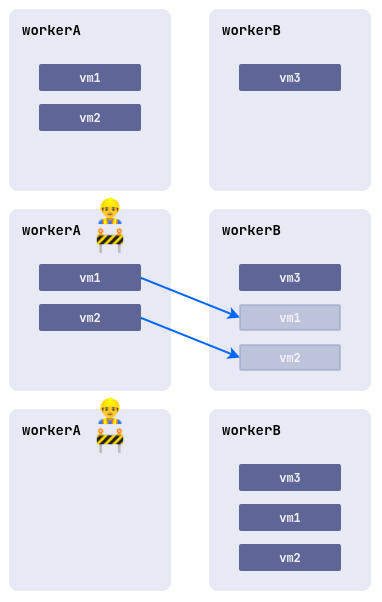
- Go to the System tab, then to Nodes.
- Select the node from the list, click the ellipsis button, and select Cordon + Drain in the menu that opens.
- To take the node out of maintenance mode, select Uncordon in the same menu.
Restarting virtual machines during node maintenance
A virtual machine can’t always be moved to another node by live migration. It can be pinned to the node by placement rules or use a device passed through from the node. The Migratable condition in the VM status shows the reason. Such a VM keeps running and holds the node, so maintenance can’t complete until the VM is restarted.
When DP finds such a VM while switching the node to maintenance mode, it adds the virtualization.deckhouse.io/virtualmachines-restart-required annotation to the node. To allow the restart, add the matching annotation to the node:
d8 k annotate node <NODE_NAME> virtualization.deckhouse.io/virtualmachines-restart-approved=""Where <NODE_NAME> is the name of the node being switched to maintenance mode.
Only the VMs that can’t be moved by live migration are restarted. The guest OS shuts down gracefully, after which the VM starts according to the .spec.runPolicy run policy. For each restart, a VirtualMachineOperation resource named node-maintenance-restart-* is created. A restart interrupts the applications inside the VM, so coordinate it with the project owners.
The approval doesn’t apply to VMs that can be moved by live migration, including those with no suitable node at the moment. Such VMs are moved by live migration as soon as a suitable node appears.
You can grant the approval in advance, while planning the work. Until the node is switched to maintenance mode, the annotation has no effect. DP removes both annotations once the node is free, so one approval covers one maintenance of one node.
DP reacts to VM eviction from a node. If eviction stopped on timeout (the .spec.nodeDrainTimeoutSecond parameter of the NodeGroup resource, 10 minutes by default), eviction isn’t retried. An approval granted after that doesn’t trigger a restart, and you have to free the node manually.
A restart frees the node but doesn’t guarantee that the VM starts on another one right away. The limitation that prevents live migration usually prevents the start on another node as well. In that case, the VM stays in the Pending phase, and the Running condition reports the reason received from the scheduler. Maintenance can continue meanwhile. The VM starts as soon as a suitable node appears, including after the node returns to service with d8 k uncordon.
The VM owner sees the same information in the EvictionRequired condition of the VM status. While the node is only being prepared for maintenance, the condition is a warning. Once eviction starts, the condition shows what happens to the VM: a move by live migration, a restart by DP, or a wait if the restart isn’t approved.
Shutting down and rebooting a node with virtual machines
Running virtual machines postpone the shutdown and reboot of their node. DP labels their workloads with pod.deckhouse.io/inhibit-node-shutdown and uses this label to delay the node shutdown. The mechanism is available in commercial DP editions, is described in the node-manager module documentation, and doesn’t need to be enabled.
If a shutdown or reboot is requested on a node that still runs virtual machines:
- The node shutdown is postponed for up to three days.
- A message about the workloads holding the shutdown is periodically printed to the node console.
On nodes where the delay mechanism works, the GracefulShutdownPostpone condition is always present. While the mechanism waits for a shutdown signal or holds the node, the condition has the True status, and once there’s nothing left to hold, it switches to False. What actually happens to the node is shown by the reason in the reason field of this condition:
WaitingForShutdownSignal: The mechanism is active and waiting for a node shutdown request.PodsWithLabelAreRunningOnNode: A node shutdown is requested and postponed, because virtual machines are still running on the node.NoRunningPodsWithLabel: No virtual machines are left on the node, there’s nothing to hold the shutdown with, and it continues.
To check the reason, run the following command:
d8 k get node <NODE_NAME> -o jsonpath='{range .status.conditions[?(@.type=="GracefulShutdownPostpone")]}{.reason}{"\n"}{end}'The shutdown delay doesn’t move virtual machines to other nodes, it only keeps the node from shutting down. For this reason, free the node from virtual machines before any work that requires a shutdown or a reboot:
-
If the VMs can be migrated, that is, the
Migratablecondition has theTruestatus, switch the node to maintenance mode withd8 k drain. -
If a VM can’t be migrated, that is, the
Migratablecondition has theFalsestatus because of local disks or devices passed through from the node, stop it withd8 v stop <VM_NAME>, and start it withd8 v start <VM_NAME>once the work is done.Stopping is available only for the
ManualandAlwaysOnUnlessStoppedManuallyrun policies. Check the VM policy:d8 k -n <NAMESPACE> get vm <VM_NAME> -o jsonpath='{.spec.runPolicy}'With the
AlwaysOnpolicy, the stop command is rejected with theNotApplicableForVirtualMachineRunPolicyreason. In that case, change the policy first, and restore the previous value once the work is done:d8 k -n <NAMESPACE> patch vm <VM_NAME> --type merge -p '{"spec":{"runPolicy":"AlwaysOnUnlessStoppedManually"}}'Where
<NAMESPACE>is the project namespace, and<VM_NAME>is the virtual machine name.
Instead of stopping VMs manually, you can let DP restart such VMs for the duration of the node maintenance. The run policy doesn’t have to be changed in that case.
If you do none of this, the node doesn’t shut down. Two alerts report this situation. The D8VirtualizationVirtualMachineHoldsNodeMaintenance alert lists the VMs that hold the node and wait for an administrator’s decision. The D8VirtualizationNodeEvacuationStuck alert fires if a VM was evicted from a node but neither migrated nor restarted within 15 minutes.
VM rebalancing
Over time, the distribution of virtual machines across nodes stops being even. The descheduler module restores the balance by moving VMs with live migration, without interrupting them. Enable this module, and the distribution is maintained without your involvement.
Rebalancing solves two tasks:
- It evens out the load. DP tracks how much CPU is reserved on each node and, when a node reserves more than 80%, moves some VMs to the nodes that reserve less than 50%.
- It restores correct placement. DP checks whether the current node meets the VM requirements and the rules of mutual VM placement. For example, if the rules forbid keeping certain VMs on the same node, the extra ones are moved.
DP sets the rebalancing parameters itself: with the descheduler module enabled, it creates a Descheduler resource named virtualization and selects in it only the machines that can be moved by live migration.
- Using the CLI
- Using the web interface
To view the rebalancing settings, run the following command:
d8 k get descheduler virtualization -o yaml- Go to the System tab, then to Configuration → Deschedulers.
- Click Create.
- In the Create resource window that opens, enter the resource name in the Name field.
- On the Configuration tab, in the Strategies block, enable the strategies you need. The Low node utilization (balancing) strategy moves VMs from overloaded nodes, while Inter-Pod Anti-Affinity violations and Node Affinity violations restore correct placement.
- Click Apply.
The created resources and the strategies enabled in them appear in the list of the section.
Rebalancing covers only the VMs that can leave their node by live migration. A VM that can’t be live migrated, for example one with a passed-through device, is never moved by rebalancing, because the only other way off the node is a restart. Such a VM is restarted only during node maintenance and only with the permission of an administrator.
ColdStandby
The ColdStandby mechanism returns a virtual machine to service after the failure of the node it was running on.
For the mechanism to work, meet two requirements:
- The
.spec.runPolicyrun policy of the virtual machine must be set toAlwaysOnUnlessStoppedManuallyorAlwaysOn. - The Fencing mechanism must be enabled on the nodes that run virtual machines.
Without Fencing, the mechanism doesn’t work. An unavailable VM doesn’t move in that case, but stays on the failed node and resumes together with it.
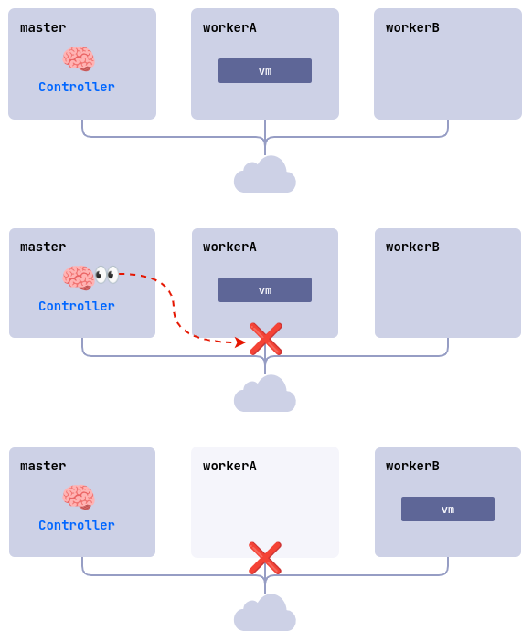
Here’s the recovery sequence, using a cluster of three nodes, master, workerA, and workerB, where Fencing is enabled on both worker nodes and the linux-vm VM runs on workerA:
- The
workerAnode fails, for example because of a power or network loss. - The controller checks node availability and finds that
workerAdoesn’t respond. - The controller removes
workerAfrom the cluster. - The
linux-vmVM starts on another suitable node,workerBin this example.
USB devices
USB device passthrough is available in commercial DP editions.
USB device passthrough to virtual machines (VMs) is handled by the virtualization-dra system component, which needs three kernel modules on the node:
usbip_coreusbip_hostvhci_hcd
DP loads them on the nodes itself. A node where all three modules are available gets the virtualization.deckhouse.io/usbip=true label, and the virtualization-dra component runs only on such nodes. If the kernel modules stop being available, the label is removed and the component is deleted from the node.
To see which nodes are ready for USB device passthrough, run the following command:
d8 k get nodes -l virtualization.deckhouse.io/usbip=trueExample output:
NAME     STATUS   ROLES    AGE   VERSION
node-1   Ready    worker   10d   v1.34.1
To verify that the component is actually running on these nodes, run the following command:
d8 k -n d8-virtualization get pods -l app=virtualization-dra -o wideA node missing from the output failed to load the kernel modules, and USB devices on that node aren’t detected. Install the kernel modules yourself from your operating system package, or build them for the kernel in use. DP detects them on its own and assigns the label to the node within a few minutes.
Path of a USB device from a node to a VM
A USB device travels from the node to a virtual machine in four steps:
-
The DRA driver detects USB devices on the nodes and publishes information about them to the Kubernetes API as a ResourceSlice. DP creates NodeUSBDevice resources from this data.
-
The administrator assigns a namespace to the NodeUSBDevice resource by setting the
.spec.assignedNamespaceparameter. This makes the device available in that namespace. -
Once the namespace is assigned, DP creates a USBDevice resource in it.
-
The project owner attaches the USBDevice device to a virtual machine by adding it to the
.spec.usbDevicesparameter of the VirtualMachine resource.
Discovered devices (NodeUSBDevice)
The NodeUSBDevice resource describes a physical USB device detected on a node. The resource exists at the cluster level, so you see all detected devices in a single list:
d8 k get nodeusbdeviceExample output:
NAME              NODE     READY   ASSIGNED   ATTACHED   NAMESPACE    AGE
usb-flash-drive   node-1   True    False      False                   10m
logitech-webcam   node-2   True    True       True       my-project   15m
The conditions in the .status.conditions block reflect the readiness of the device and its state. The Ready and Attached conditions match the USBDevice conditions, and the Assigned condition shows whether a namespace is assigned to the device:
Available: No namespace is assigned.InProgress: A namespace is assigned and the USBDevice resource is being created.Assigned: The USBDevice resource is created and the device is available in the namespace.
Assigning a namespace to a USB device
Until a namespace is assigned to a device, the project owner doesn’t see it. To make the device available in a project, follow these steps.
-
Connect the USB device to a node that is ready for passthrough and wait for a NodeUSBDevice resource to appear.
-
Assign the namespace with the
.spec.assignedNamespaceparameter:d8 k apply -f - <<EOF apiVersion: virtualization.deckhouse.io/v1alpha2 kind: NodeUSBDevice metadata: name: logitech-webcam spec: assignedNamespace: my-project EOF -
Verify that a USBDevice resource appears in the namespace:
d8 k get usbdevice -n my-project
After that, the project owner attaches the device to a virtual machine.
Viewing USB device details
Full details about a device and its current state are available in the resource status.
When a device is physically disconnected from the node, the Attached condition gets the False value, and the Ready condition gets the NotFound reason. The same is reflected in the status of the USBDevice resource in the project namespace.
- Using the CLI
- Using the web interface
The device identifiers, its location, and the current conditions are stored in the resource status:
d8 k get nodeusbdevice <DEVICE_NAME> -o yamlWhere <DEVICE_NAME> is the name of the NodeUSBDevice resource.
To get only the device attributes, query the fields you need directly:
d8 k get nodeusbdevice <DEVICE_NAME> \
  -o jsonpath='{.status.attributes.manufacturer}{" "}{.status.attributes.product}{" ("}{.status.attributes.vendorID}{":"}{.status.attributes.productID}{")\n"}'
Example output:
Logitech Webcam C920 (046d:082d)
- Go to the System tab, then to Virtualization → Node USB devices.
- Review the list, which shows the device status, manufacturer, product, serial number, node, bus, device number, and assigned namespace.
The project owner sees the devices assigned to their project in the Virtualization → USB devices section of that project.
Requirements and limitations
When planning USB device passthrough, consider the following requirements and limitations:
- A node where USB devices must be detected has to carry the
virtualization.deckhouse.io/usbip=truelabel and run containerd version 2, otherwise thevirtualization-dracomponent doesn’t start there. - A device is passed to a virtual machine over the network using USBIP, so the VM can run on a node other than the one the device is physically connected to.
- Only a device that reports the USB 2.0 speed (480 Mbps) or a USB 3.x speed (5 Gbps and higher) can be passed through. DP doesn’t let you attach a slower device to a VM, for example a mouse or a keyboard at 1.5 or 12 Mbps.
- A node connects no more than 16 devices, 8 per USB 2.0 hub and 8 per USB 3.0 hub.
- The hub is selected by the device speed and can’t be changed manually. A USB 2.0 device doesn’t connect to a USB 3.0 hub, and vice versa.
- A device can be attached to a running VM and detached from it without stopping the VM.
GPU devices
GPU device passthrough is an experimental feature available in commercial DP editions.
DP attaches physical GPU devices to virtual machines using DRA (Dynamic Resource Allocation). A project owner requests a device by a reference to a GPUClass in the .spec.gpus block of their machine, and you prepare the cluster for this.
To make passthrough work, provide the following:
- Kubernetes 1.34 or later with the DRA feature gates required by your cluster configuration.
- The
GPUfeature gate in thevirtualizationmodule settings. - The enabled
gpumodule in the DRA mode, which is set by thedra.enabledparameter. - A
GPUClassresource that selects devices of the model you need. Thegpumodule creates a DeviceClass resource with the same name from it, and the device is allocated to a machine through that class.
To enable the feature gate, add it to the module settings:
apiVersion: deckhouse.io/v1alpha1
kind: ModuleConfig
metadata:
  name: virtualization
spec:
  settings:
    featureGates:
      - GPU
After that, tell the project owners the names of the available GPUClass resources. A single machine takes no more than 16 devices, and a change to the .spec.gpus block applies only after the machine restarts.
PCI devices
PCI device passthrough is available in commercial DP editions.
PCI device passthrough lets you attach a physical device of a node to a virtual machine (VM), for example an industrial controller, a hardware security module, a capture card, an FPGA, or an entire network card. In the guest operating system, such a device works under its own driver, so a VM can use the hardware DP doesn’t support directly.
A device reaches a machine in two steps. First you assign it to a project namespace, and then the project owner lists the device in the specification of their machine. The device is granted for exclusive use, so it’s available in one namespace and to one machine only.
DP switches the device drivers itself, and you don’t need to configure them on the node manually. When a machine starts, DP unbinds the device from the regular kernel driver and binds it to the vfio-pci driver, and once the machine is stopped, it returns the device to the regular driver. While the machine is running, the node doesn’t use the device.
Node requirements
PCI device passthrough is handled by the virtualization-dra-pci system component. It runs only on nodes with containerd version 2 and hardware I/O virtualization enabled. DP checks the nodes itself and assigns the virtualization.deckhouse.io/vfio=true label to the suitable ones.
To enable hardware I/O virtualization, turn on VT-d on Intel or AMD-Vi on AMD in the node BIOS and add the intel_iommu=on or amd_iommu=on kernel parameter.
To see which nodes are ready for PCI device passthrough, run the following command:
d8 k get nodes -l virtualization.deckhouse.io/vfio=true,virtualization.deckhouse.io/containerd-version=v2Example output:
NAME     STATUS   ROLES    AGE   VERSION
node-1   Ready    worker   10d   v1.34.1
A node missing from the output has not been assigned the label. Check the /sys/kernel/iommu_groups directory on it. An empty directory means that hardware I/O virtualization is disabled. Enable it and reboot the node, and the label is assigned automatically within a few minutes.
To verify that the component is actually running on these nodes, run the following command:
d8 k -n d8-virtualization get pods -l app=virtualization-dra-pci -o wideAssigning a namespace to a PCI device
DP detects the devices on the suitable nodes and creates a NodePCIDevice resource for each of them. The component scans the PCI bus at startup and then every five minutes, so a newly installed device appears in the list within a few minutes.
To make a device available to a project, follow these steps.
-
Find the device among the detected ones:
d8 k get nodepcideviceExample output:
NAME                                            NODE     ADDRESS        READY   ASSIGNED   ATTACHED   NAMESPACE    AGE
pci-4f2c0b1e8d9a3c5b7e1f0a2d4c6b8e0f1a3c5d7e    node-1   0000:3b:00.0   True    False      False                   10m
pci-9a1b3c5d7e9f0a2b4c6d8e0f1a3b5c7d9e1f0a2b    node-2   0000:65:00.0   True    True       False      my-project   15m
The resource name is a hash of the device parameters and the node name, so look up the device you need by the
NODEandADDRESScolumns. To verify the choice, use the.status.attributesblock, which holds the PCI bus address and the vendor and model identifiers. They let you find the same device in thelspci -nnoutput on the node. -
Assign a namespace with the
.spec.assignedNamespaceparameter:d8 k apply -f - <<EOF apiVersion: virtualization.deckhouse.io/v1alpha2 kind: NodePCIDevice metadata: name: pci-4f2c0b1e8d9a3c5b7e1f0a2d4c6b8e0f1a3c5d7e spec: assignedNamespace: my-project EOF -
Make sure that a PCIDevice resource has appeared in the namespace:
d8 k get pcidevice -n my-project
After that, the project owner attaches the device to their machine by specifying the PCIDevice resource name in the .spec.pciDevices parameter of the VirtualMachine resource.
To make the device unavailable to the project, clear the .spec.assignedNamespace parameter or set a different namespace. The PCIDevice resource in the previous namespace is deleted.
While the device is listed in a machine specification, the PCIDevice resource isn’t deleted and the machine keeps running. Ask the project owner to remove the device from the specification. If you set a different namespace instead of clearing the parameter, the resource appears in it right away, but the machine of the new project stays in the Pending phase while the device is occupied by the previous machine.
Requirements and limitations for PCI devices
When planning PCI device passthrough, consider the following requirements and limitations:
- Passthrough works in a cluster with Kubernetes 1.34 or higher and containerd version 2 on the nodes, and the
DRAResourceClaimDeviceStatus,DRADeviceBindingConditions, andDRAConsumableCapacityfeature gates have to be enabled in kube-apiserver. - DP doesn’t detect every device of a node, because the hardware the node itself depends on stays at its disposal. The following devices never appear in the list:
- Display adapters, which are passed through as GPU devices.
- Devices integrated into the chipset, bridges, memory controllers, and system peripherals.
- Network controllers with active interfaces.
- Storage controllers whose disks are used by the node.
- Devices that share an IOMMU group with any of the above, because a group goes to the VM as a whole.
- A VM starts only on the node that holds the device attached to it, so all its PCI devices have to be on the same node, otherwise the specification is rejected.
- A VM with a PCI device can’t be moved by live migration, and the
Migratablecondition gets theVirtualMachineHostDevicesNotMigratablereason, so such machines have to be stopped before the node is put into maintenance. - Devices are attached when the VM starts, so a change to the
.spec.pciDevicesparameter requires its restart. - A single device is attached to one VM only, and a VM takes no more than eight devices.
- A network card that’s passed through works around the cluster network subsystem. It doesn’t appear in the
.spec.networksparameter, and DP neither assigns nor tracks its IP and MAC addresses.
Security event audit
The audit records actions on virtual machines (VMs) and on the module itself, so that you can investigate an incident and reconstruct the sequence of events.
Available in commercial DP editions.
Enabling the audit
To enable the security event audit, follow these steps:
-
Enable the
log-shipperandruntime-audit-enginemodules. -
Enable the Kubernetes API audit by setting
.spec.settings.apiserver.auditPolicyEnabledtotruein thecontrol-plane-managermodule. -
Set
.spec.settings.audit.enabledtotruein thevirtualizationmodule:spec: settings: audit: enabled: true
Until all three conditions are met, the audit component doesn’t start in the cluster. For the other parameters, see the module settings.
Event types
The event type is recorded in the type field. The audit distinguishes the following types:
Access to VM: A connection to a VM over the console, VNC, or port forwarding. Both the start and the end of the session are recorded.Manage VM: Creating, updating, or deleting a VirtualMachine resource.Control VM: A change of the VM state, including start, stop, restart, migration, and eviction through the VirtualMachineOperation resource, as well as a shutdown or restart from the guest OS and an abnormal termination.Module control: Creating, updating, disabling, or deleting a ModuleConfig.Virtualization control: Creating or deleting a system component of the module in thed8-virtualizationnamespace.Integrity check: A mismatch between the VM configuration checksum and the reference one.Forbidden operation: An attempt to perform a forbidden operation.
Regardless of the type, every event contains the same fields:
name: A description of what happened.datetime: The time of the event.request_subject: The user or ServiceAccount that performed the action.operation_result: The result of the operation.uid: The identifier of the record in the Kubernetes audit.
Additional fields depend on the event type. For example, VM events contain the virtual_machine_name and virtual_machine_namespace fields, while forbidden operations report the request source in the source_ip field and the denial reason in the forbid_reason field.
Viewing events
Events are collected by the virtualization-audit system component in the d8-virtualization namespace. To forward them to the cluster logging system, for example to Loki, create a ClusterLoggingConfig:
apiVersion: deckhouse.io/v1alpha1
kind: ClusterLoggingConfig
metadata:
  name: virtualization-audit-logs
spec:
  destinationRefs:
    - d8-loki
  kubernetesPods:
    namespaceSelector:
      matchNames:
        - d8-virtualization
    labelSelector:
      matchLabels:
        app: virtualization-audit
  type: KubernetesPods
To view the events in Grafana, use a Loki query:
{namespace="d8-virtualization", pod=~"virtualization-audit-.*"}